| Sign In | Join Free | My carsrow.com |
|
| Sign In | Join Free | My carsrow.com |
|
| Categories | P+F Sensors |
|---|---|
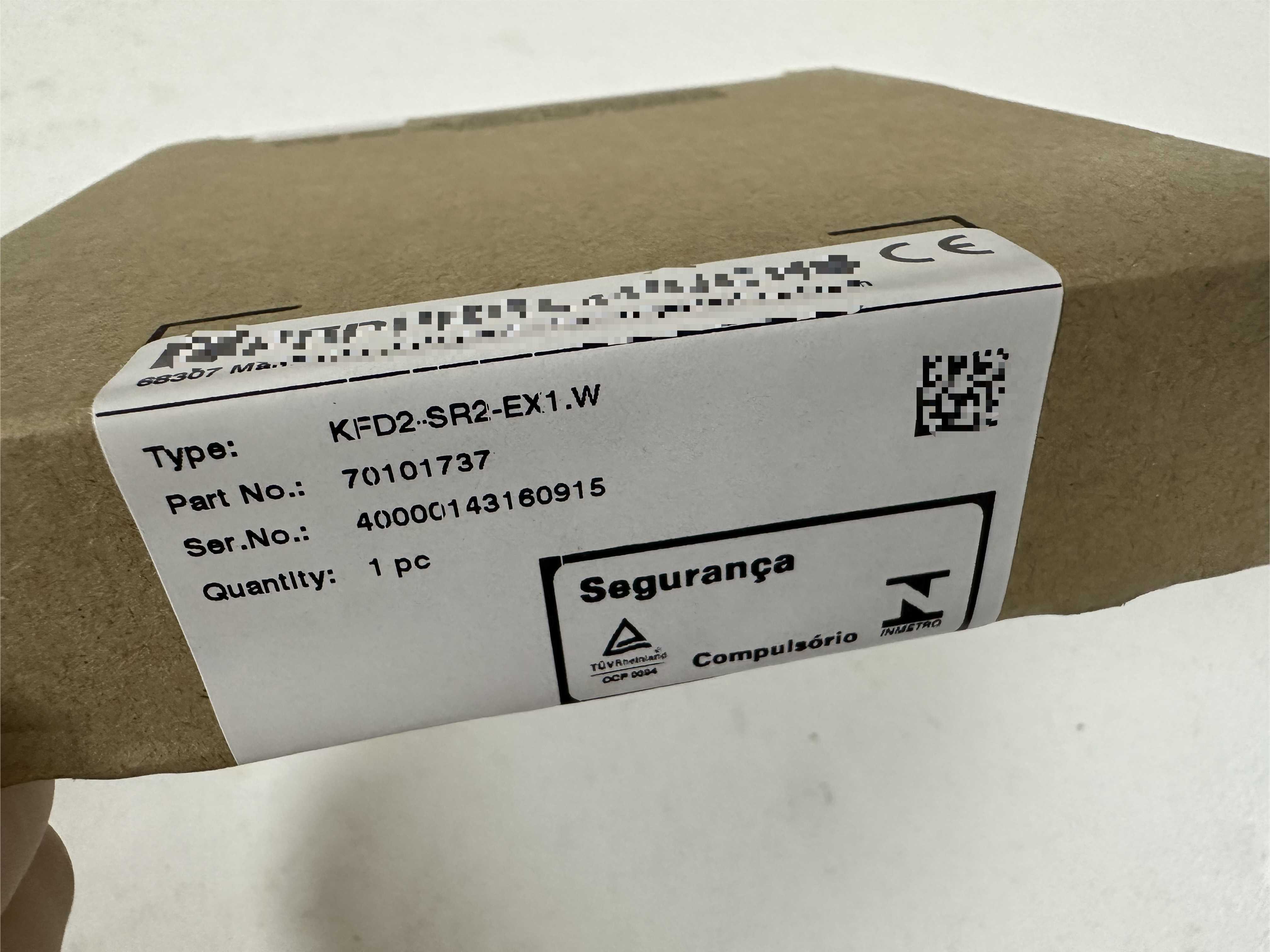
| Brand Name: | P+F |
| Model Number: | KFD2-SR2-Ex1.W |
| Certification: | PF 08 CERT 0803 |
| Place of Origin: | Germany |
| MOQ: | 1 piece |
| Price: | negotiable |
| Payment Terms: | T/T |
| Supply Ability: | 100pcs per month |
| Delivery Time: | on request |
| Packaging Details: | standard carton packing |
| Safety Integrity Level (SIL): | SIL 2 |
| Supply Connection: | Power Rail or terminals 14+, 15- |
| Supply Rated current: | ≤ 35 mA |
| Switching frequency: | < 10 Hz |
| Display elements: | LEDs |
| Electromagnetic compatibility: | NE 21:2017 , EN 61326-3-1:2017 , EN IEC 61326-3-2:2018 |
| Ambient temperature: | -40 ... 70 °C (-40 ... 158 °F) |
| Dimensions: | 20 x 119 x 115 mm (0.8 x 4.7 x 4.5 inch) (W x H x D) , housing type B2 |
| Company Info. |
| SC Automation Limited |
| Verified Supplier |
| View Contact Details |
| Product List |
1-channel isolated barrier, 24 V DC supply (Power Rail), Dry contact or NAMUR inputs, Relay contact output, Line fault detection (LFD), Reversible mode of operation, Up to SIL 2 (SC 3) acc. to IEC/EN 61508, Housing width: 20 mm, Number of channels: 1-channel, Safety Integrity Level (SIL): SIL 2, Systematic capability (SC): SC 3, Rated voltage: 19 ... 30 V DC, Field device: NAMUR sensor, Field device [2]: volt-free contact, Line fault detection, Type: 1 x relay (change-over contact)
Technical Data
General specifications | ||
|---|---|---|
Signal type | Digital Input | |
Functional safety related parameters | ||
Safety Integrity Level (SIL) | SIL 2 | |
Systematic capability (SC) | SC 3 | |
Supply | ||
Connection | Power Rail or terminals 14+, 15- | |
Rated voltage | 19 ... 30 V DC | |
Ripple | ≤ 10 % | |
Rated current | ≤ 35 mA | |
Power dissipation | ≤ 0.7 W | |
Power consumption | ≤ 0.7 W | |
Input | ||
Connection side | field side | |
Connection | terminals 1+, 2+, 3- | |
Rated values | acc. to EN 60947-5-6 (NAMUR) | |
Open circuit voltage/short-circuit current | approx. 8 V DC / approx. 8 mA | |
Switching point/switching hysteresis | 1.2 ... 2.1 mA / approx. 0.2 mA | |
Line fault detection | breakage I ≤ 0.1 mA , short-circuit I > 6 mA | |
Pulse/Pause ratio | min. 20 ms / min. 20 ms | |
Output | ||
Connection side | control side | |
Connection | terminals 7, 8, 9 | |
Output | signal ; relay | |
Contact loading | 250 V AC/2 A/cos φ > 0.75; 126.5 V AC/4 A/cos φ > 0.75; 40 V DC/2 A resistive load | |
Minimum switch current | 2 mA / 24 V DC | |
Energized/De-energized delay | approx. 20 ms / approx. 20 ms | |
Mechanical life | 107 switching cycles | |
Collective error message | Power Rail | |
Transfer characteristics | ||
Switching frequency | < 10 Hz | |
Galvanic isolation | ||
Input/Output | reinforced insulation according to IEC/EN 61010-1, rated insulation voltage 300 Veff | |
Input/power supply | reinforced insulation according to IEC/EN 61010-1, rated insulation voltage 300 Veff | |
Output/power supply | reinforced insulation according to IEC/EN 61010-1, rated insulation voltage 300 Veff | |
Indicators/settings | ||
Display elements | LEDs | |
Control elements | DIP switch | |
Configuration | via DIP switches | |
Labeling | space for labeling at the front | |
Directive conformity | ||
Electromagnetic compatibility | ||
Directive 2014/30/EU | EN 61326-1:2013 (industrial locations) | |
Low voltage | ||
Directive 2014/35/EU | EN 61010-1:2010+A1:2019+A1:2019/AC:2019 | |
Conformity | ||
Electromagnetic compatibility | NE 21:2017 , EN 61326-3-1:2017 , EN IEC 61326-3-2:2018 | |
Degree of protection | IEC 60529:1989+A1:1999+A2:2013 | |
Functional safety | IEC/EN 61508:2010 | |
Input | EN 60947-5-6:2000 | |
Ambient conditions | ||
Ambient temperature | -40 ... 70 °C (-40 ... 158 °F) | |
Mechanical specifications | ||
Degree of protection | IP20 | |
Connection | screw terminals | |
Mass | approx. 150 g | |
Dimensions | 20 x 119 x 115 mm (0.8 x 4.7 x 4.5 inch) (W x H x D) , housing type B2 | |
Height | 119 mm | |
Width | 20 mm | |
Depth | 115 mm | |
Mounting | on 35 mm DIN mounting rail acc. to EN 60715:2001 | |
Data for application in connection with hazardous areas | ||
EU-type examination certificate | PTB 00 ATEX 2080 | |
Marking |
| |
Input | Ex ia | |
Voltage | 10.5 V | |
Current | 13 mA | |
Power | 34 mW (linear characteristic) | |
Supply | ||
Maximum safe voltage | 253 V AC / 125 V DC (Attention! Um is no rated voltage.) | |
Output | ||
Maximum safe voltage | 253 V AC (Attention! The rated voltage can be lower.) | |
Fault indication output | ||
Maximum safe voltage | 40 V DC (Attention! Um is no rated voltage.) | |
Certificate | PF 08 CERT 0803 | |
Marking |
| |
Input | Ex ic | |
Voltage | 10.5 V | |
Current | 13 mA | |
Power | 34 mW (linear characteristic) | |
Certificate | TÜV 99 ATEX 1493 X | |
Marking |
| |
Galvanic isolation | ||
Input/Output | safe electrical isolation acc. to IEC/EN 60079-11, voltage peak value 375 V | |
Input/power supply | safe electrical isolation acc. to IEC/EN 60079-11, voltage peak value 375 V | |
Directive conformity | ||
Directive 2014/34/EU | EN IEC 60079-0:2018+AC:2020 , EN 60079-7:2015+A1:2018 , EN 60079-11:2012 , EN IEC 60079-15:2019 | |
International approvals | ||
FM approval | ||
FM certificate | FM19US0207X | |
Control drawing | 116-0035 | |
UL approval | E106378 | |
Control drawing | 116-0473 (cULus) | |
Contact loading | 250 V AC/2 A/cos φ > 0.75; 126.5 V AC/4 A/cos φ > 0.75; 30 V DC/2 A resistive load | |
IECEx approval | ||
IECEx certificate | IECEx PTB 11.0034 , IECEx TUN 19.0013X | |
IECEx marking | [Ex ia Ga] IIC | |
Related Models:
KFD0-CS-Ex1.51P | NBB8-18GM50-A2-V1 |
KFD0-CS-Ex2.50P | NBB8-18GM50-E0 |
KFD0-CS-Ex2.51P | NBB8-18GM50-E0-V1 |
KFD0-RO-Ex2 | NBB8-18GM50-E2 |
KFD0-SCS-Ex1.55 | NBB8-18GM50-E2-V1 |
KFD0-SD2-Ex2.1045 | NBB8-18GM50-E2-V1-M |
KFD0-SD2-Ex2.1245 | NBB8-18GM60-A2-V1 |
KFD0-TR-Ex1 | NBB8-18GM60-US |
KFD0-CC-1 | NBN3-8GM40-E2-V3 |
KFD0-HMS-16 | NBN3-F25F-E8-V1 |
KFD0-RSH-1.4S.PS2 | NBN40-U1K-N0 |
KFD0-SD2-EX1.10100 | NBN40-U4LK-N0 |
KFD0-SD2-EX1.1045 | NBVB15-U1.Z2 |
KFD2-UT2-1 | NCB5-18GM40-NO |
KFD2-CD-1.32 | NJ10-30GM-N-5M |
KFD2-CD-EX1.32 | NJ15-30GK-N |
KFD2-HMM-16 | NJ2-12GK-SN |
KFD2-SH-EX1.T | NJ2-12GM-N |
KFD2-UT2-1 | RD0-FB-EX4.COM |
KFD2-VR4-EX1.26 | SC3,5-G-N0 |
KFU8-UFC-1.D | SC3,5-G-N0-5M |
V15-G-2M | SC3,5-G-N0-6M |
Z 787 | SJ3,5-N |
Z787.H | SJ3,5-S1N |
HIC2031 | UPR-03 |
Z787.H.F | SJ3,5-N-BU |


|
