| Sign In | Join Free | My carsrow.com |
|
| Sign In | Join Free | My carsrow.com |
|
| Categories | Closed Loop Hall Effect Current Sensor |
|---|---|
| Brand Name: | TOKEN |
| Model Number: | TBC-DHT |
| Certification: | CE;ROHS |
| Place of Origin: | CHINA |
| MOQ: | 10pcs |
| Price: | Price Reconsideration |
| Supply Ability: | 2.2K pcs per month |
| Packaging Details: | Little Carton Size:34*23*21CM;240pcs/Carton ;Large Carton Size:48*37*26CM;480pcs/Carton |
| application: | Uninterruptible Power Supplies |
| Mounting Type: | PCB Mounting |
| Principle: | null balance |
| Standard: | high precision |
| product name: | Hall Effect Current Sensor |
| Operating temperature: | -40~+85 |
Pulsed Current Low Current Hall Effect Sensor For Uninterruptible Power Supplies
TBC-DHT series current sensor is a closed loop device based on the measuring principle of the hall effect and null balance method, with a galvanic isolation between primary and secondary circuit. It provides accurate electronic measurement of DC, AC or pulsed currents.
| Electrical data(Ta=25℃±5℃) |
| Type Parameter | TBC25DHT | TBC50DHT | Unit |
Rated input (Ipn) | 25 | 50 | A |
Measure current range(Ip) | 60 | 120 | A |
Secondary Turns(Ns) | 1000±1 | 2000±2 | T |
Secondary resister | 40 | 80 | Ω |
Rated output (Isn) | @ Ip=±Ipn ±25±0.5% | mA | |
Supply voltage | ±15±5% | V | |
| Power consumption | ≤20+Ip/Ns | mA | |
Zero Offset current | @ Is=0 ±0.2 | mA | |
Offset current drift | @ -40~+85℃ ≤±0.6 | mA | |
| Linearity | @ Ip=0-±Ipn ≤0.1 | %FS | |
Total precision | ≤±0.7 | %FS | |
di/dt accurately followed | >50 | A/µS | |
Response time | @ Ip=Ipn,50 A/µS,10%-90% <1 | µS | |
Bandwidth | @ -1db DC~100 | KHZ | |
Galvanic isolation | @ 50HZ,AC,1min 2.5 | KV | |
| Applications |
AC variable speed drives
Static converters for DC motor drives
Battery supplied applications
Uninterruptible Power Supplies (UPS)
Switched Mode Power Supplies(SMPS)
Power supplies for welding applications
| Mechanical dimension(for reference only) |
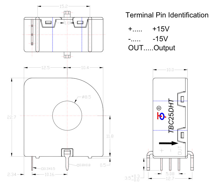
Remarks:
1. All dimensions are in mm.
2. General tolerance ±1mm
| Directions for use |
When the current will be measured goes through a sensor, the voltage will be measured at the output end.
(Note: The false wiring may result in the damage of the sensor)
Custom design in the different rated input current and the output voltage are available.
Standards |
| General date |
| Value | Unit | Symbol | |
| Operating temperature | -40 to +85 | ºC | TA |
| Storage temperature | -40 to +125 | ºC | TS |
| Mass(approx) | 9 | g | M |
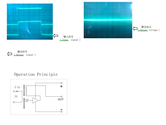
| Characteristics chart |
Pulse current signal response characteristic Effects of impulse noise

|
